|
The central instrument cluster on a classic mini and many classic cars utilize a mechanical voltage regulator (stabilizer) to provide a constant 10v to the instruments. Variance in the supply voltage will cause an internal bimetallic strip to change shape making the internal contacts connect or disconnect ensuring a constant 10v is supplied. Overtime the mechanical nature of the regulator can wear causing failure and an unreliable voltage output. The convenience and cheapness of modern electronics makes it possible to replace the mechanical regulator with a solid state unit i.e. no moving parts. 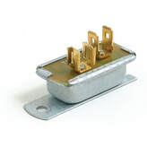 Standard mechanical voltage stabilizer
0 Comments
TIme for an overhaul
My original Arduino speedometer was created back in November 2015 and I was very pleased with it at the time. It received a lot of interest via this website and YouTube. However, the perfectionist in me was never happy with how the original version turned out, The construction was a bit hacked together and the code was far from elegant.
The mini shell being away for restoration for such a long time, fast approaching a year as I type, gave me the perfect opportunity to revisit some of my earlier work. It was time for an overhaul. I am including everything here so you can create your own version of my speedometer. During my research I would often find examples of what I was trying to achieve that were lacking in detail or incomplete. I hope this resource proves useful to someone and saves you some time. Everything offered here is to be used at your own risk. I do not accept responsibility for any mistakes I might have made that cause you to make the same mistakes. If there is enough interest I would consider supplying the circuit boards and components in kits so you can create your own. Get in contact if interested. 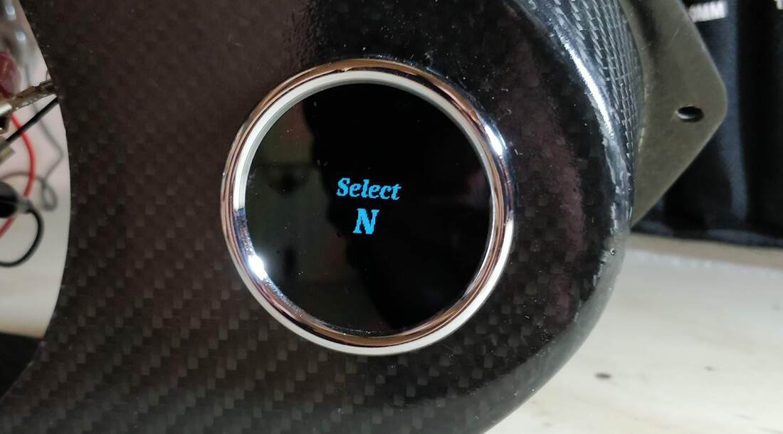 This is the final version of my Arduino controlled gear position gauge. I've refined the design over the last couple of years to a point that I was happy to commit to having a printed circuit board manufactured.
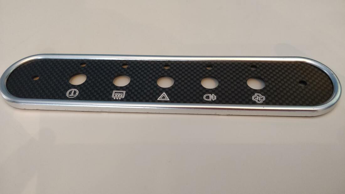 In an effort to tie the interior together I have made this carbon fibre switch panel to match the carbon centre speedometer. I used my new CNC machine to engrave the logos and mill the holes accurately. The logos were created by downloading suitable png icons and converting them to svg's using Inkscape so they could be imported into Fusion360 and used to create tool paths. Once everything was machined I highlighted the logos by applying white enamel and then carefully wiping the excess away. Switch FunctionsFrom left to right, the switches functions are;
- Multi gauge - Used to toggle between different gauge screens and acknowledge/dismiss warnings. - Heated rear screen - Hazards - Rear fog light - Fan - Manual override to turn the radiator fan on. 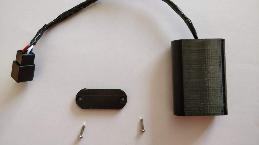 This is my Arduino controlled exup eliminator that will fool the Yamaha R1 ECU into thinking the exup valve is still connected thus preventing error code 17 on appearing on the gauge. How it worksIt has been a lot of work getting to this point. Lots of wires have been stripped out of the loom and modifications made so it can be run in the mini.
The video says it all. It lives!!!! The fault codes are expected. I don't have an exup, air or water temp sensor connected to the loom. 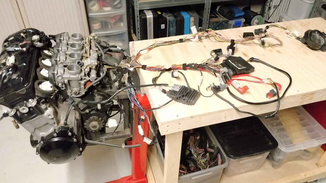 With the wiring loom modifications mostly complete it was time to offer it up to the engine and get it all the major components hooked up. The plan is to connect it to a battery so I can power up and check everything out and keep an eye on the fault codes if any appear.
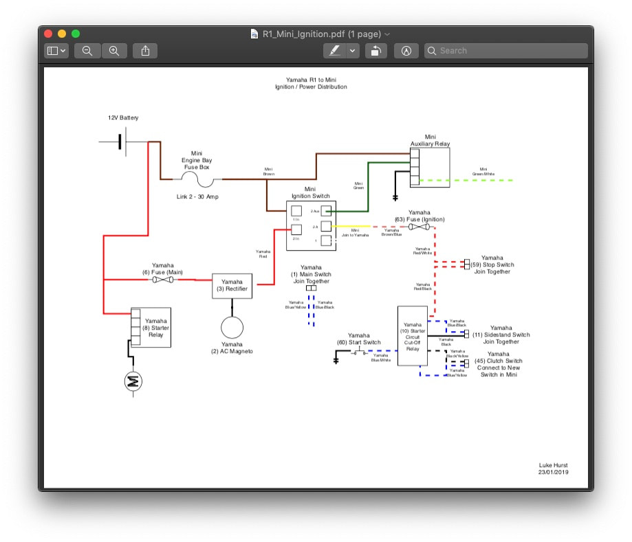 I have lost count of how many hours I have spent studying the Yamaha wiring loom. Hopefully it will pay off and I've come up with what should be a viable method of connecting the R1 loom to the Mini ignition/power distribution.
After a few very cold evenings spent in my garage I have just about stripped everything I can from the loom and I have identified all the main components. Before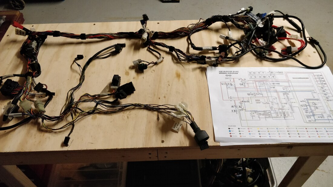 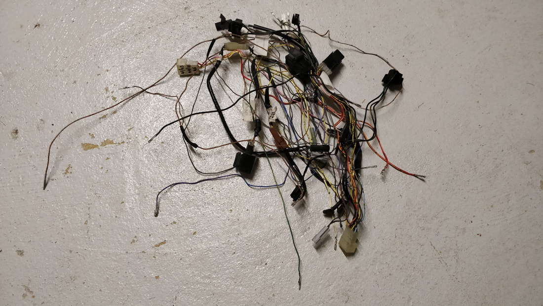 Progress with the R1 loom is being made. The picture shows all the wiring I have removed from the loom so far. Items removed from loom |
