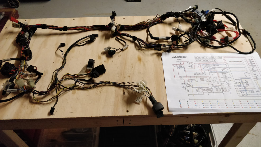
 The huge task of sorting out the Yamaha R1 wiring loom has begun. I've started by removing almost all of the wrap covering the individual wires to make tracing and indentification easier.
The general idea is to identify all of the wires and then start stripping out the circuits that aren't required such as the lighting and horn. To identify the wires I am using a combination of the official Yamaha wiring diagram along with the Haynes manual version for my 2003 5PW engine. Once the loom is stripped back to essential circuits I will begin the task of converting it to car use such as disabling the lean sensor.
2 Comments
 It has been a few years since I created the first Arduino speedometer and during that time I have improved my Arduino coding a lot as well as now having a 3D printer so I think its time to make some improvements.
I've just finished adding a programmable rev gauge to my carbon centre speedo. All the hard programming work was the handy work of Chippernut
I built v2.31 of Chippernut's project on a protoboard and decided to make the 7-segment display and rotary encoder removable. Here are a few pictures of the build process. I have been playing around with an Arduino for a little while now attempting to make my own gear position indicator and here is the almost finished product.
It consists of a 1.3" OLED mounted inside a re-purposed Smiths oil temp gauge that I picked up on theminiforum.co.uk for £10. I have gone down this route so that the gauge looks "factory" once installed and isn't obvious what it is. It will be installed in my carbon fibre centre binnacle.
The above video shows the final assembly of the speedometer with a 555 timer providing a simulated 60mph for calibration. The odometer reading is read from EEPROM upon startup and displayed on the OLED. Each time the speed = 0mph it will be written back to EEPROM.
Parts List
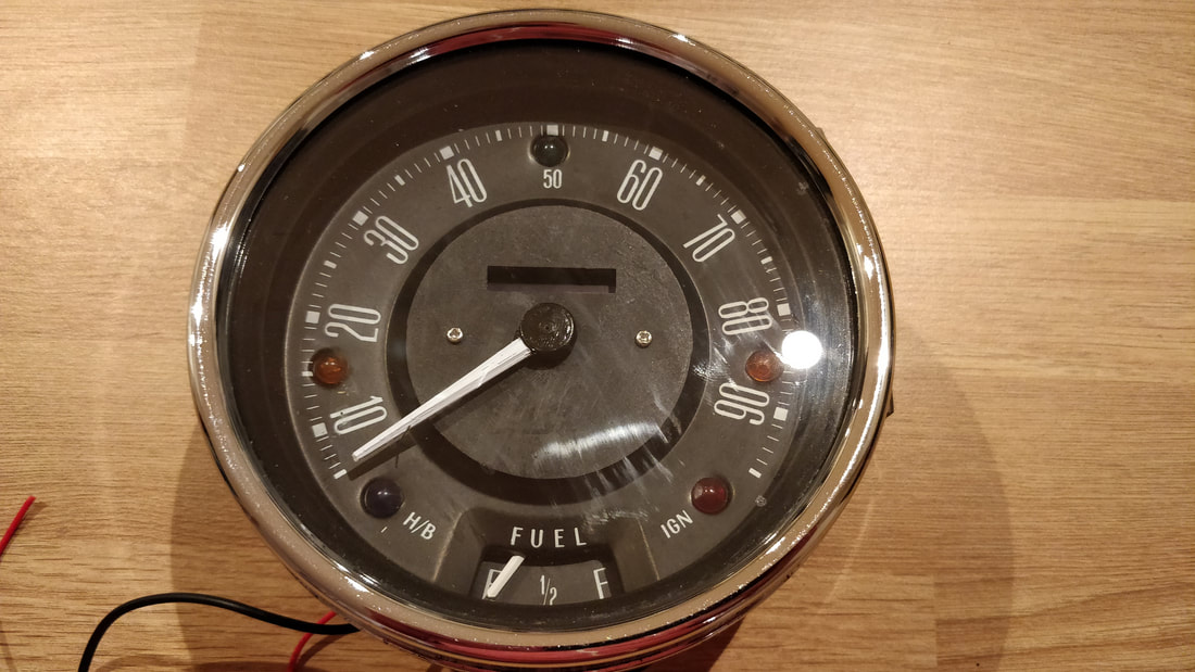
The original plan to use a DC motor to spin a standard Smiths speedometer cable has gone out the window. The DC motor I purchased didn't have enough torque to spin the cable at the required speed and the slightest bend in the cable stalled the motor.
Version 2 will consist of a stepper motor controlled pointer needle for the speed output. The code is written and stepper motor is on order. I will post a video and parts list once I have the prototype built. This next problem to overcome was how to keep track of distance. Luckily during my research I found a couple of projects that were using the Arduino to count distance covered and then write that value to EEPROM ready for the next restart. The above video is my implementation of various sketches into a working combination for me. I will post up the code once I have the stepper motor hooked up and tested. I have never been a fan of the ugly brake test switch in the mini taking up dash space, rarely used but required for the MOT and safety of course! but who remembers to press it each time before you go for a drive? The conversion I am carrying out to toggle switches has given me the opportunity to re-design the brake test circuit that will completely remove the need for a manual switch. The idea is to have a handbrake operated switch so a warning lamp is illuminated each time the handbrake is applied or more importantly if the brake fluid is dangerously low. This is how modern cars work so here is my circuit design to achieve the same in the mini. A quick update to show the progress I've made with the carbon toggle switch conversion. I will be adding labels under the switches once I've decided the order. The centre silver push button will be the engine start button. 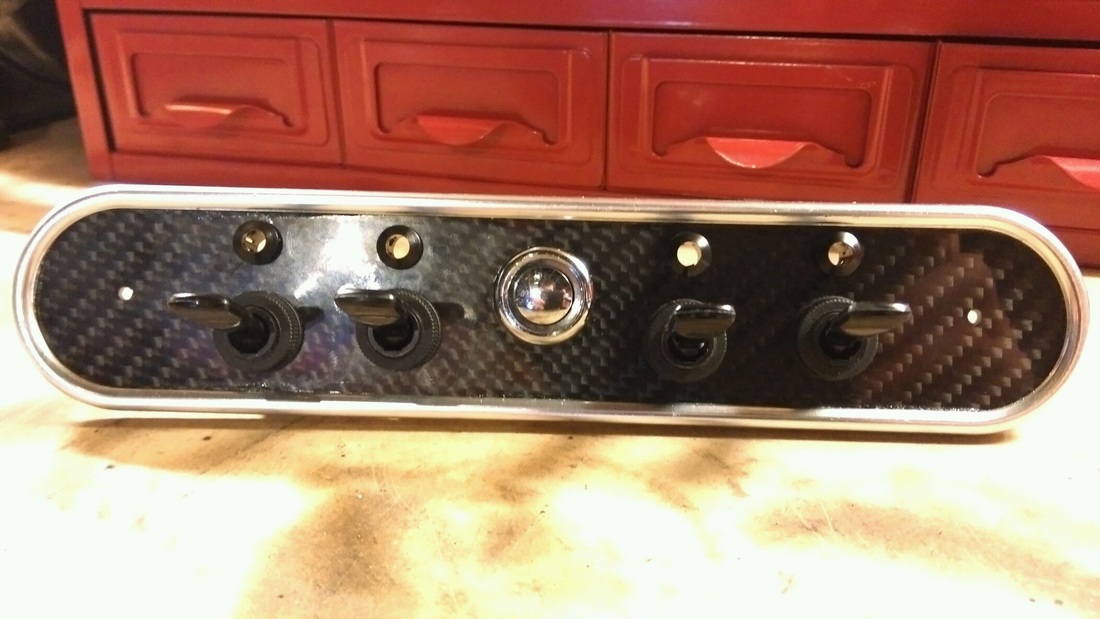 Continuing with Arduino development I decided to have a bash at making a gauge that could monitor all the vital systems in the car but would fit in with the period looks. The obvious way to go is to mount an OLED inside a stripped out Smiths gauge which will be mounted in my carbon centre binnacle. I bit of googling turned up this project page with some code that I could easily adapt to for my own use. A big thanks to Boris for publishing his code. Whilst I am waiting for the DC motor to arrive that I'll be using on the Smiths speedometer project I thought I would see what else I can use the Arduino for. Although I'll be running the R1 clocks mounted behind the steering wheel, I also thought it would be quite cool to convert a standard looking Smiths 52mm gauge into a gear indicator. Normally these sorts of things can be picked up on eBay for £15 but they are ugly and wouldn't work with my interior. Working prototype |
