|
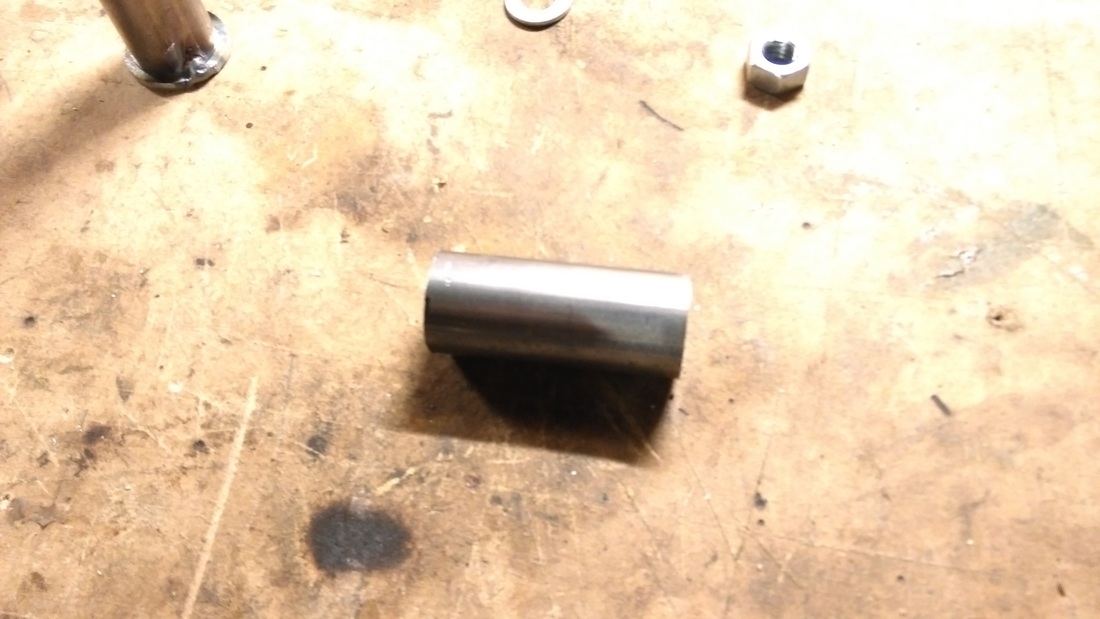
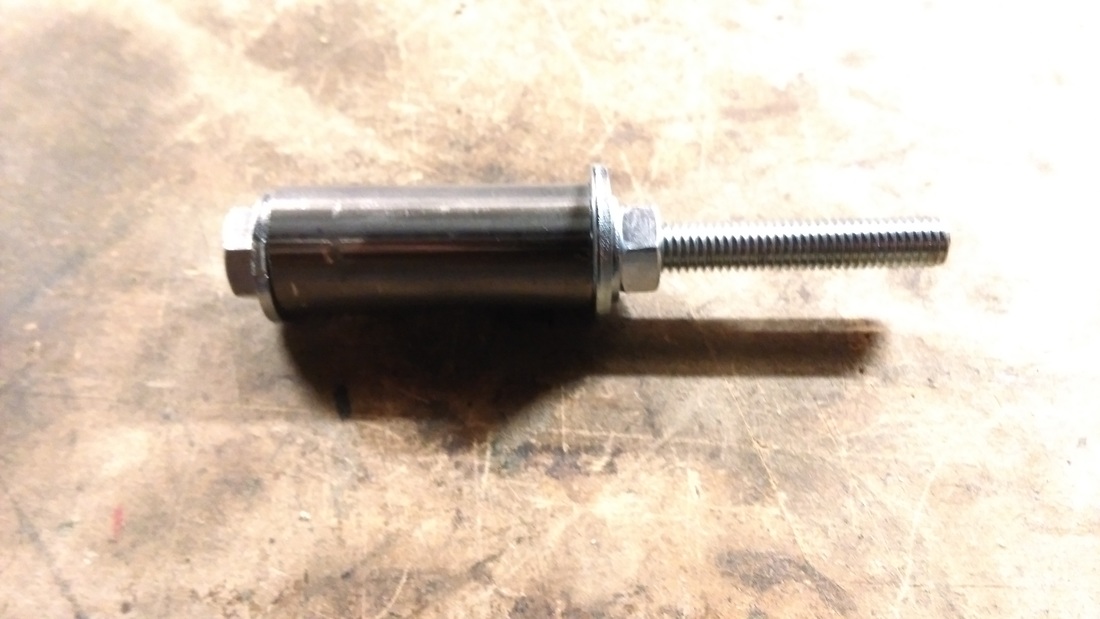
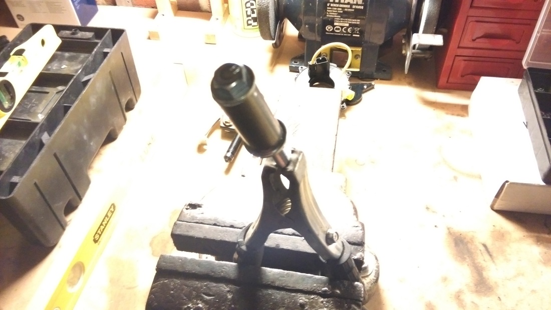
The most important bit of the build so far and perhaps the most critical to success is the differential hanger. It will ensure the correct chain-line and tension whilst the power of the engine is transferred through the chain into the drive shafts. My design attempts to overcome the challenges of having a solid mounting point whilst remaining compact enough to fit between the engine and subframe. FabricationI created a cardboard template of the chain-line between the engine sprocket and the rear differential sprocket. This allowed me to determine the amount of space I would need between the hanger and the differential. I also needed to ensure the hanger was the correct width once the differential is fitted so I measured and cut a block of wood to the same size as the diff to act as a spacer. 88mm to be exact. Once I had determined all the spacing, I marked out the critical dimensions on a piece of cardboard to help with the metal box section cuts. 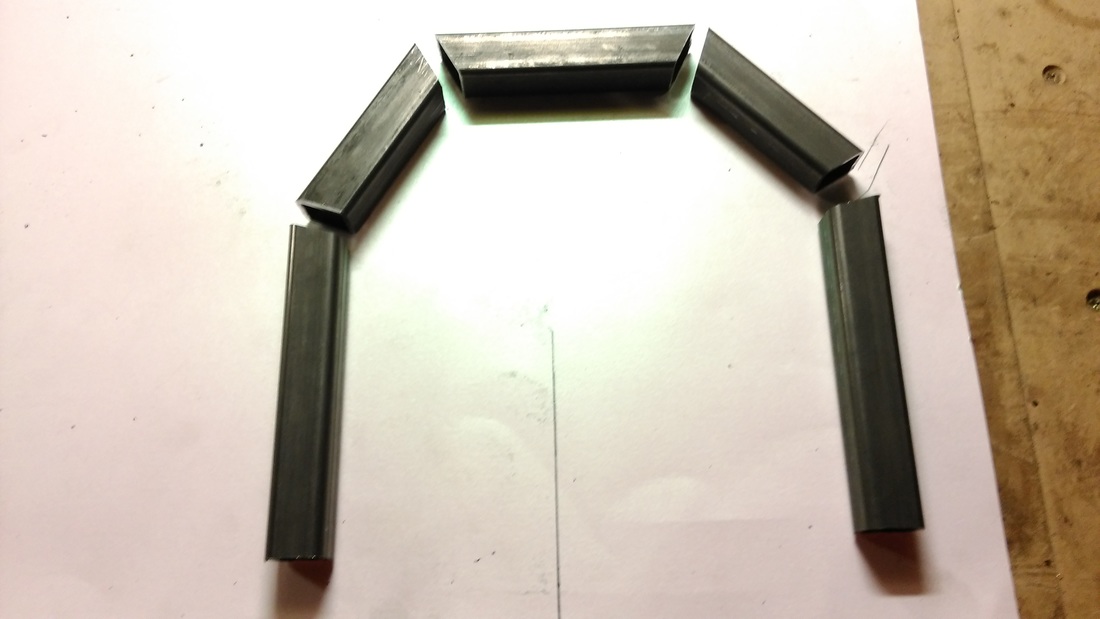 The pencil line was used to mark the hanger width from the right-hand cardboard edge.
0 Comments
The original plan to use a DC motor to spin a standard Smiths speedometer cable has gone out the window. The DC motor I purchased didn't have enough torque to spin the cable at the required speed and the slightest bend in the cable stalled the motor.
Version 2 will consist of a stepper motor controlled pointer needle for the speed output. The code is written and stepper motor is on order. I will post a video and parts list once I have the prototype built. This next problem to overcome was how to keep track of distance. Luckily during my research I found a couple of projects that were using the Arduino to count distance covered and then write that value to EEPROM ready for the next restart. The above video is my implementation of various sketches into a working combination for me. I will post up the code once I have the stepper motor hooked up and tested. So a few days ago I discovered the engine cradle I built had an issue - the engine was sitting two low relative to the subframe resulting in the differential being too close to the engines front sprocket which in turn would result in a very short chain and poor ground clearance. One approach would be extending the current cradle by adding in the required extra metal but the question is how much higher did the engine need to sit and would I be happy hacking the current cradle around. I decided to start again and take the opportunity to build a better cradle. I was never happy with the look of the first one anyway and the overall finish is still important even if it was functional. Not having a finished install to hand or knowing anyone with one I couldn't simply ask someone to measure their setup so I started studying photos and discovered that the front mounted oil cooler bolt was approx 5mm lower than the top of the front subframe cross-member. I fashioned a plinth for the engine to sit on using scrap wood and window fitting packers that come in various thicknesses (1mm-6mm) and have proven very handy. I figured I needed the engine to sit 30mm higher than the lowest part of the subframe. I also picked the front of the engine up slightly (an extra 6mm) to improve clearance on the cars front cross panel. 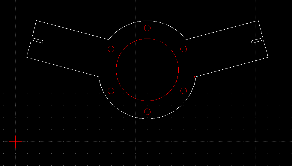 Although I have quite a way to go until I will need to install a gear shifter I do need to think about it as it will effect fabrication, wiring layout etc..... I was originally going to fabricate my own mechanical shifter like the one sold with other conversion kits. Something like this; 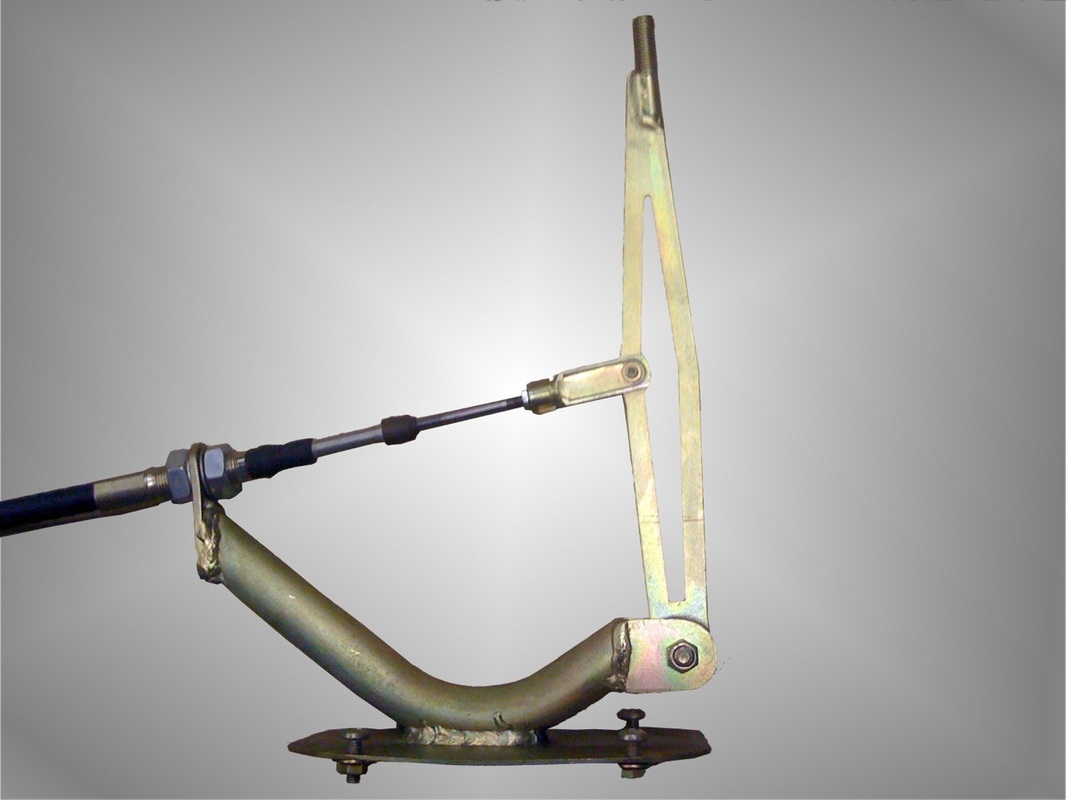 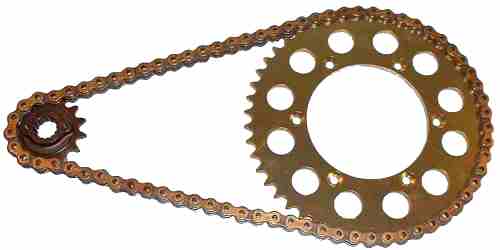 As I've mentioned in an earlier post, I have been working on a digital-to-analog converter that will enable me to "drive" a mechanical Smiths centre speedo. In order for the whole thing to work I need to accurately convert the digital output from the R1 engine to a RPM (revolution per minute) factor that turns the mechanical cable.
Here are the maths I have been working on. These might not be accurate and I will hopefully receive the DC motor soon so I can test it all out. Known variables; Front Sprocket = 14 tooth Rear Sprocket = 41 tooth 1 mile = 63360 inches Smiths Speedometer TPM (Turns Per Mile) 1248 Wheel circumference based on tyre size;
I have never been a fan of the ugly brake test switch in the mini taking up dash space, rarely used but required for the MOT and safety of course! but who remembers to press it each time before you go for a drive? The conversion I am carrying out to toggle switches has given me the opportunity to re-design the brake test circuit that will completely remove the need for a manual switch. The idea is to have a handbrake operated switch so a warning lamp is illuminated each time the handbrake is applied or more importantly if the brake fluid is dangerously low. This is how modern cars work so here is my circuit design to achieve the same in the mini. |