|
I have been playing around with an Arduino for a little while now attempting to make my own gear position indicator and here is the almost finished product.
It consists of a 1.3" OLED mounted inside a re-purposed Smiths oil temp gauge that I picked up on theminiforum.co.uk for £10. I have gone down this route so that the gauge looks "factory" once installed and isn't obvious what it is. It will be installed in my carbon fibre centre binnacle.
1 Comment
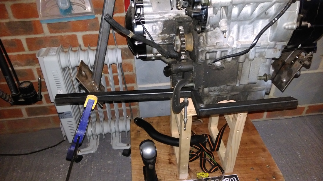
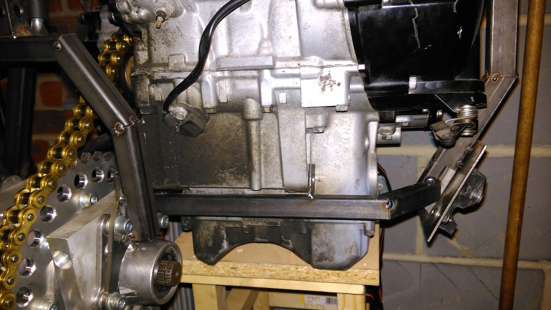
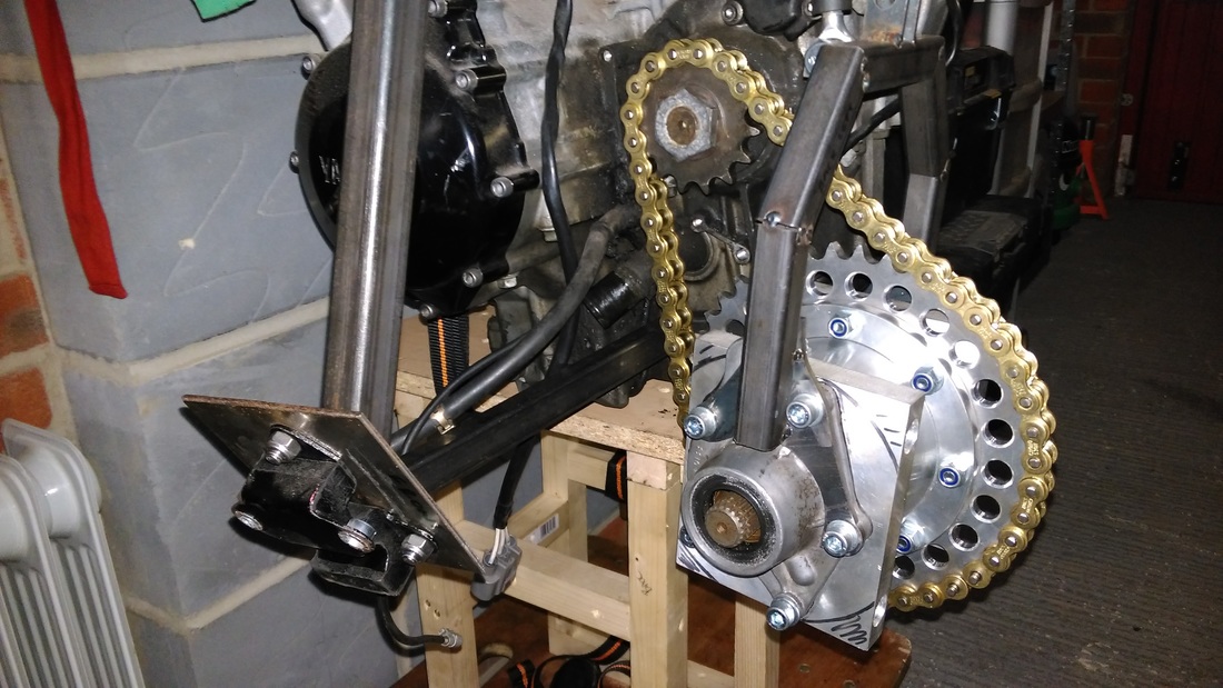
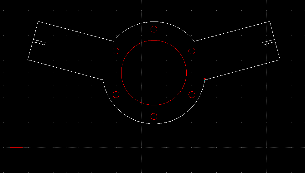
Quite a lot of work has been carried out on the hanger since my last update. The initial design wasn't working out that well due to the top rose joint allowing the whole assembly to pivot upwards affecting the chain tension. The next few pictures will show the evolution of what I hope to be the final solution. The real test will be installing everything in the car but so far it's working out well. The original idea 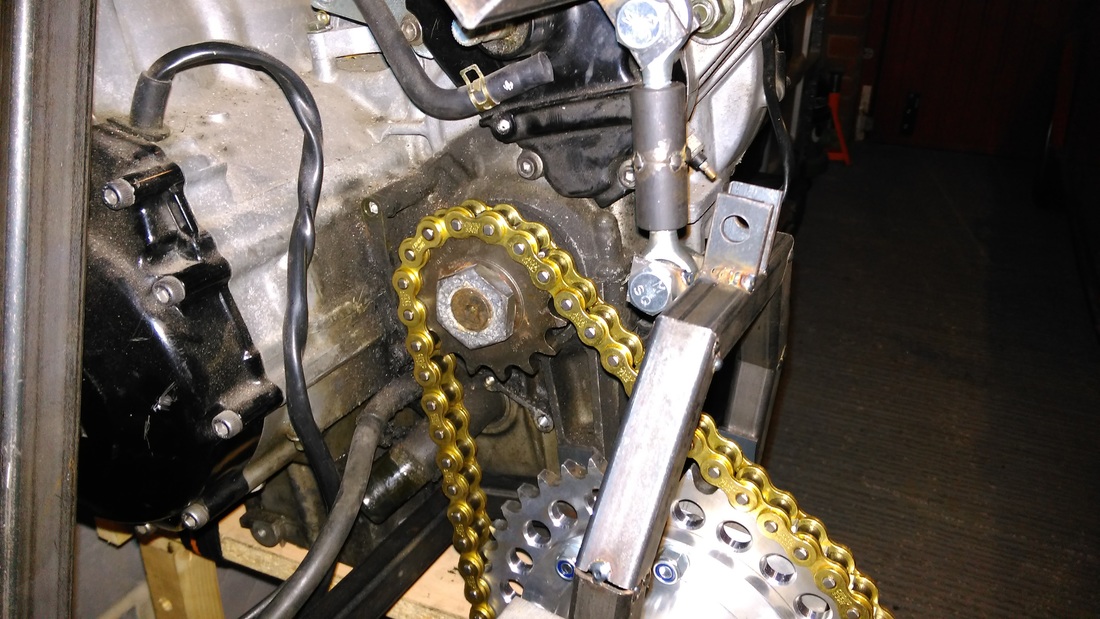 Managed to get some more done on the cradle on Sunday. I tackled the lower engine mount cross-member and mounts. It was tricky to get all the angles accurate as whilst ensuring it lined up with the engine mount holes due to all the different angles at it each contact point. Chain clearance is good and bottom rad hose is clear. Picking up from where I left Part 1 this next phase of the diff hanger fabrication is perhaps the most critical aspect as it involves mounting the hanger to the engine cradle perfectly in-line with the front engine sprocket. I had figured out in my head that I would use some rose joints and an adjustable link bar as the upper mount. The link bar would allow me to shorten or lengthen mount which would effectively raise or lower the diff thus adjusting the tension of the chain. 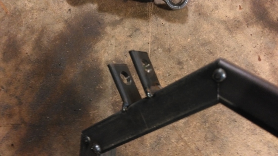 The first job was making some tabs for the rose joint to attach to. I cut some 3mm flat-bar into 30mm lengths, clamped them together and drilled a 8mm hole using a drill press. The centre of the hanger was marked and the tabs were tacked so that the rose joint centre lined up with the hanger centre line.
 Although I have quite a way to go until I will need to install a gear shifter I do need to think about it as it will effect fabrication, wiring layout etc..... I was originally going to fabricate my own mechanical shifter like the one sold with other conversion kits. Something like this; 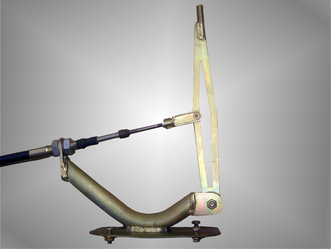 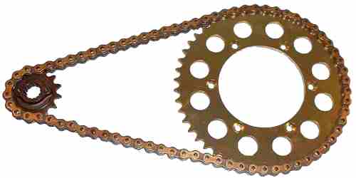 As I've mentioned in an earlier post, I have been working on a digital-to-analog converter that will enable me to "drive" a mechanical Smiths centre speedo. In order for the whole thing to work I need to accurately convert the digital output from the R1 engine to a RPM (revolution per minute) factor that turns the mechanical cable.
Here are the maths I have been working on. These might not be accurate and I will hopefully receive the DC motor soon so I can test it all out. Known variables; Front Sprocket = 14 tooth Rear Sprocket = 41 tooth 1 mile = 63360 inches Smiths Speedometer TPM (Turns Per Mile) 1248 Wheel circumference based on tyre size;
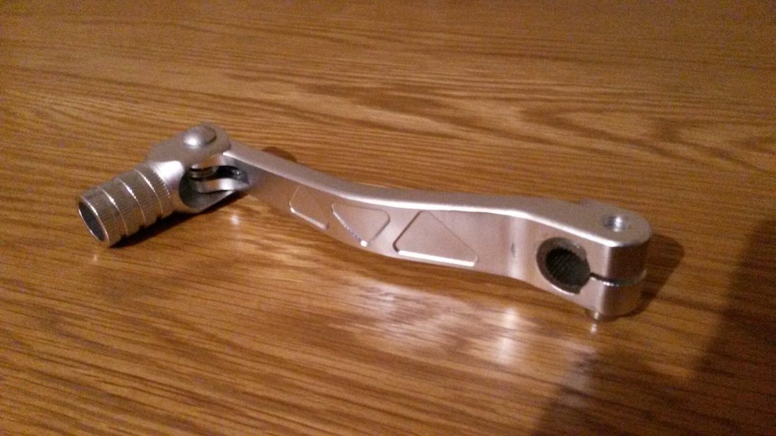 My new shifter arrived for the Yamaha R1 engine I'll soon be installing in the Cooper :-)
I haven't gone into much detail yet about my plans to install a Yamaha R1 engine in the front of the Cooper. I decided to go down this route over Christmas 2014 and a week later I had a 2003 R1 injection engine sitting in my garage. More to follow.... |