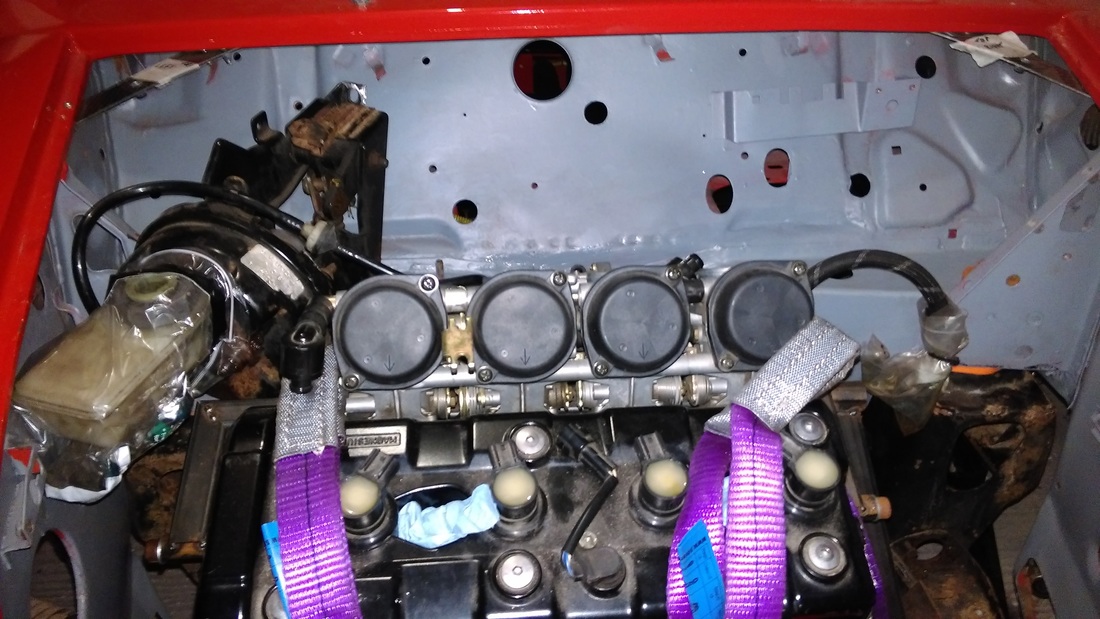
 Well look at that. One Yamaha R1 5PW fuel-injected 1000cc bike engine sitting under it's own support in the front of my Mini Cooper!!
Oh and whats that I see. An offset brake servo :-)
0 Comments
Picking up from where I left Part 1 this next phase of the diff hanger fabrication is perhaps the most critical aspect as it involves mounting the hanger to the engine cradle perfectly in-line with the front engine sprocket. I had figured out in my head that I would use some rose joints and an adjustable link bar as the upper mount. The link bar would allow me to shorten or lengthen mount which would effectively raise or lower the diff thus adjusting the tension of the chain. 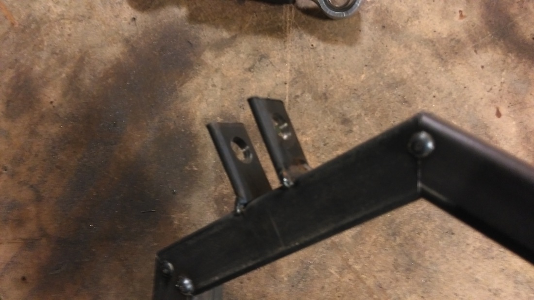 The first job was making some tabs for the rose joint to attach to. I cut some 3mm flat-bar into 30mm lengths, clamped them together and drilled a 8mm hole using a drill press. The centre of the hanger was marked and the tabs were tacked so that the rose joint centre lined up with the hanger centre line.
The above video shows the final assembly of the speedometer with a 555 timer providing a simulated 60mph for calibration. The odometer reading is read from EEPROM upon startup and displayed on the OLED. Each time the speed = 0mph it will be written back to EEPROM.
Parts List
|
