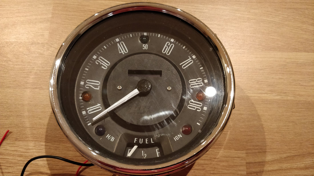
 It has been a few years since I created the first Arduino speedometer and during that time I have improved my Arduino coding a lot as well as now having a 3D printer so I think its time to make some improvements.
6 Comments
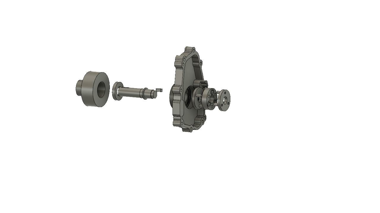
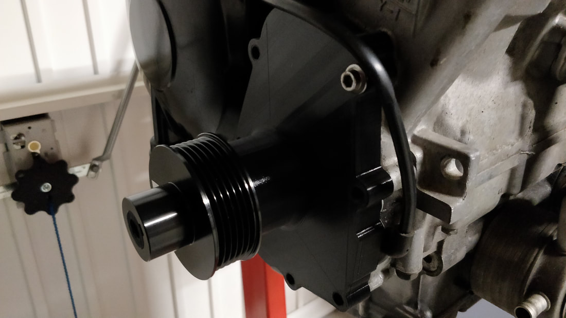 Good progress is being made on the supercharger prototype. I managed to get all the custom parts printed up so a test fit was possible. A bearing and oil seal will still need to be fitted but that didn't stop a quick trial fit. 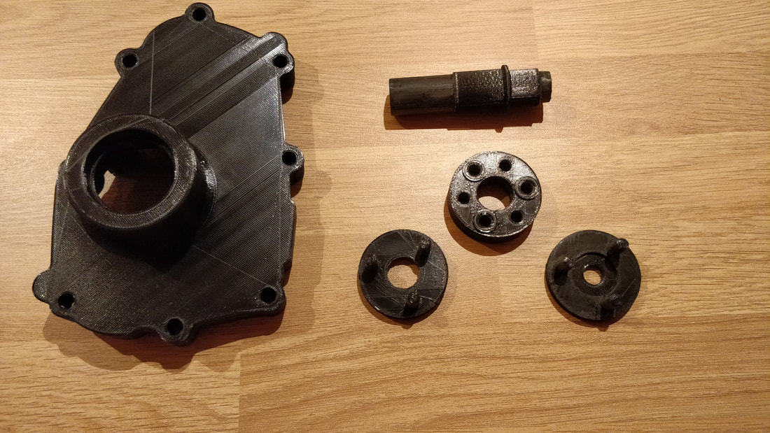 The main components shown here consist of the custom couplers I've designed, a custom shaft and a custom engine casing. I also printed up a cush coupler so I don't damage the one I will be using in the finished product.
 Transplanting a Yamaha R1 engine into a classic mini might be a little crazy but wouldn't a supercharged one be even better?!
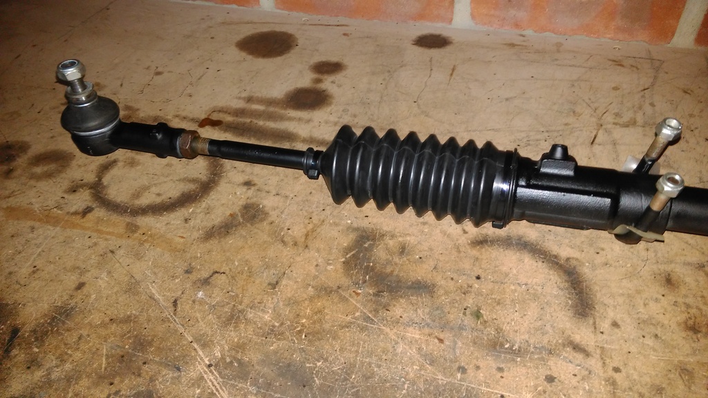
Following a ride in my friends new Lotus Exige S I couldn't get the idea of having a supercharger out of my head. The noise and torque is so addictive. I started conducting a little research and couldn't find much for inspiration. A company called TTS Performance produce a supercharger kit for later R1's but sadly not for my 2003 5PW engine. Not letting the lack of off-the-shelf kits get in my way I have set about creating my own! The main obstacle to overcome is finding a way to get drive from the engine to power the supercharger. Sadly the standard R1 engine does not have any external pulleys to use so I needed to come up with a solution. I've been a little slack updating this website but progress has been made behind the scenes in a number of areas. I will keep this update brief and go into more detail in later posts. Steering Rack OverhaulThe steering rack was in fairly good mechanical condition before the car came off the road so I didn't see any great need to replace it. It did however need a fresh coat of paint. Upon closer inspection it also needed at least one new rubber boot. I've just finished adding a programmable rev gauge to my carbon centre speedo. All the hard programming work was the handy work of Chippernut
I built v2.31 of Chippernut's project on a protoboard and decided to make the 7-segment display and rotary encoder removable. Here are a few pictures of the build process. I have been playing around with an Arduino for a little while now attempting to make my own gear position indicator and here is the almost finished product.
It consists of a 1.3" OLED mounted inside a re-purposed Smiths oil temp gauge that I picked up on theminiforum.co.uk for £10. I have gone down this route so that the gauge looks "factory" once installed and isn't obvious what it is. It will be installed in my carbon fibre centre binnacle. Quite a lot of work has been carried out on the hanger since my last update. The initial design wasn't working out that well due to the top rose joint allowing the whole assembly to pivot upwards affecting the chain tension. The next few pictures will show the evolution of what I hope to be the final solution. The real test will be installing everything in the car but so far it's working out well. The original idea 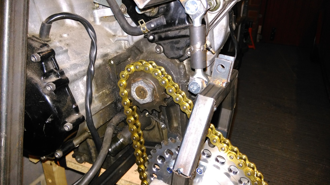  No I am not going to be writing about the UK mobile phone operator! I am turning my attention to the R1 engine breathing requirements.
A number of BECs (Bike Engine Cars) use sausage filters, socks or unfiltered trumpets. Sticking with my theory that I probably can't design things better than Yamaha manged and the fact that the engine would of used an airbox whilst in the bike, I thought I would stick with the same idea and use an airbox. Using an airbox will have the added benefit of reducing the induction noise and it will allow me to direct cool air into the throttle bodies rather than picking up warm air from the engine bay. The question is what sort of airbox, what size and what size airduct ?  Although I am still quite a way off from installing the engine in the car and subsequently plumbing in the cooling system, I have started to think about how I might approach it so that I do all the required fabrication before I paint the engine bay or powder coat the engine frame.
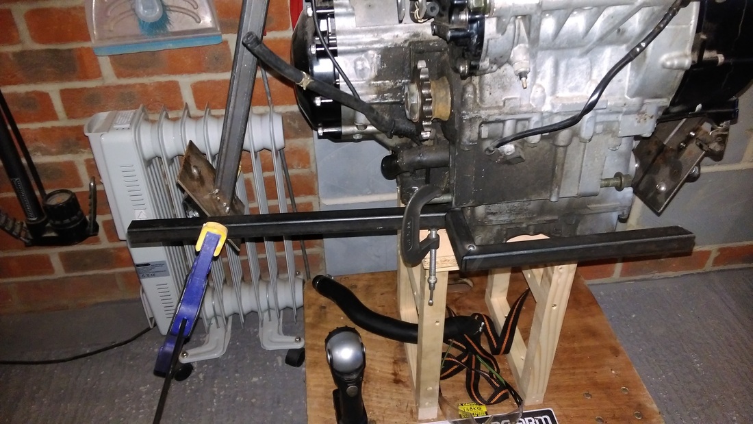
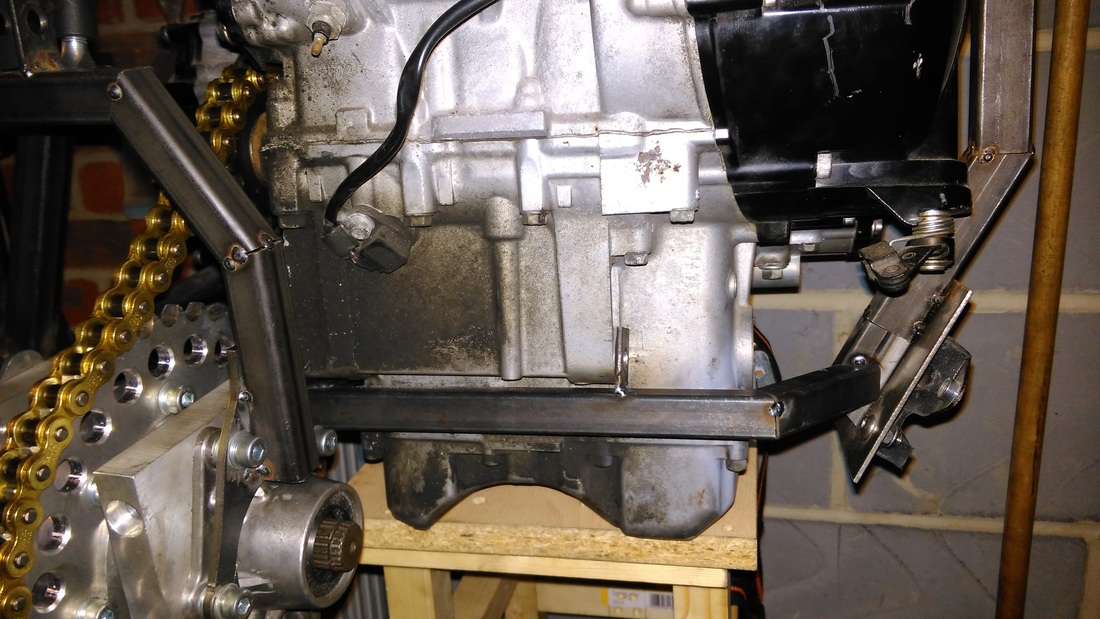
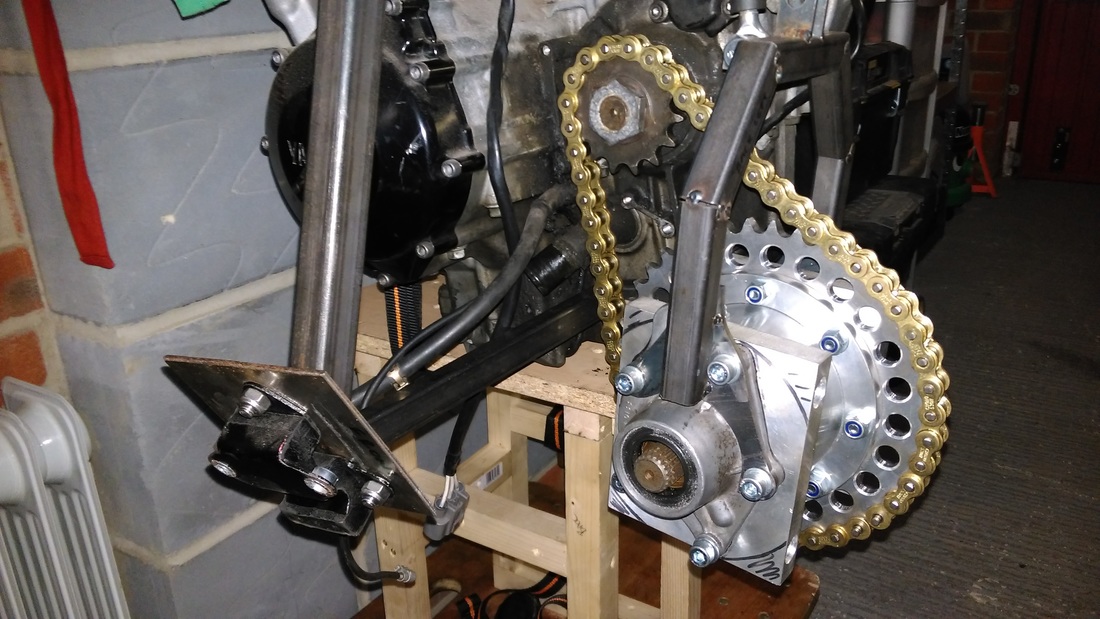
Managed to get some more done on the cradle on Sunday. I tackled the lower engine mount cross-member and mounts. It was tricky to get all the angles accurate as whilst ensuring it lined up with the engine mount holes due to all the different angles at it each contact point. Chain clearance is good and bottom rad hose is clear. |