|
Continuing with Arduino development I decided to have a bash at making a gauge that could monitor all the vital systems in the car but would fit in with the period looks. The obvious way to go is to mount an OLED inside a stripped out Smiths gauge which will be mounted in my carbon centre binnacle. I bit of googling turned up this project page with some code that I could easily adapt to for my own use. A big thanks to Boris for publishing his code.
0 Comments
Whilst I am waiting for the DC motor to arrive that I'll be using on the Smiths speedometer project I thought I would see what else I can use the Arduino for. Although I'll be running the R1 clocks mounted behind the steering wheel, I also thought it would be quite cool to convert a standard looking Smiths 52mm gauge into a gear indicator. Normally these sorts of things can be picked up on eBay for £15 but they are ugly and wouldn't work with my interior. Working prototypeWell it's been quite a while since I updated this blog so I thought I'd share what I've been up to. I've made quite a lot of progress with the build which includes starting lots of little sub-projects.
I have recently turned my hand to Arduino which is proving to be both fun to develop and it's opened a whole new world of possibilities. I started thinking about how I am going to drive the mechanical Smiths speedometer once I have the bike engine installed. The R1 motor uses a digital pulse to drive the standard clocks (which I will be running in the car) but that's no good for the mechanically driven Smiths gauge. An simple post on the Mini Forum resulted in someone suggesting I look at Arduino. Well fast forward a couple of weeks I have got a prototype code that will take the digital pulse from the R1, count it over a 1 second interval, convert to MPH, convert that to RPM to drive a DC motor connected to Smiths speedo cable to drive the gauge. It's essentially a digital-to-analog converter. I haven't been able to test it properly as I am still waiting for a DC motor to arrive but I will write up in more detail including my calculations and code when it's working. I purchased this carbon fibre composite sheet on eBay so I can make a new switch panel for the new toggle switches. It is 2mm thick and is made up of a carbon layer on fibreglass to keep costs down and provide the desired cosmetic appearance. 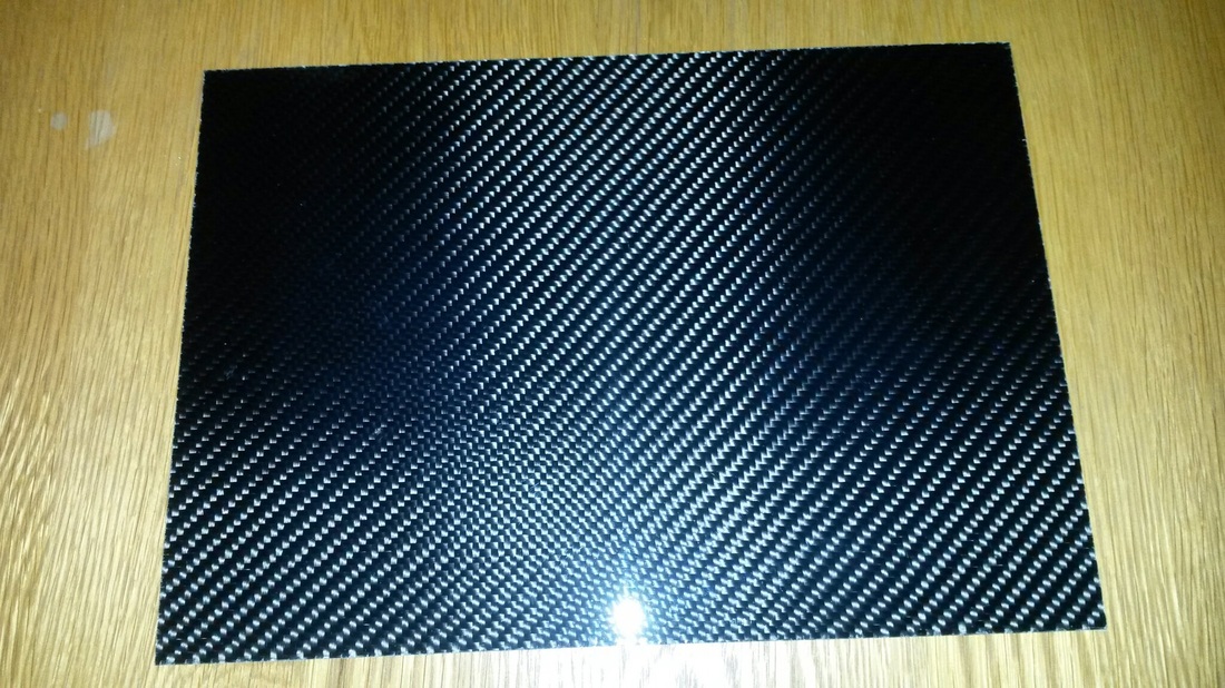
As part of my quest to add a few MK1 styling touches with my own little twist I decided I would replace the standard square rocker switches with the something a little more retro. The MK1's had a lever toggle switches with a ignition key in the centre of the switch panel. I will need to retain the standard ignition mainly for the steering lock which is an MOT requirement however, I am going to add a start button in the centre of the switch panel which is required as part of the Yamaha R1 loom. The standard rocker switches come in various configurations to suit the circuit they are switching. Although a range of toggle switches are available as direct replacements I realised I could use standard off:on toggles if I modified the circuits a little. 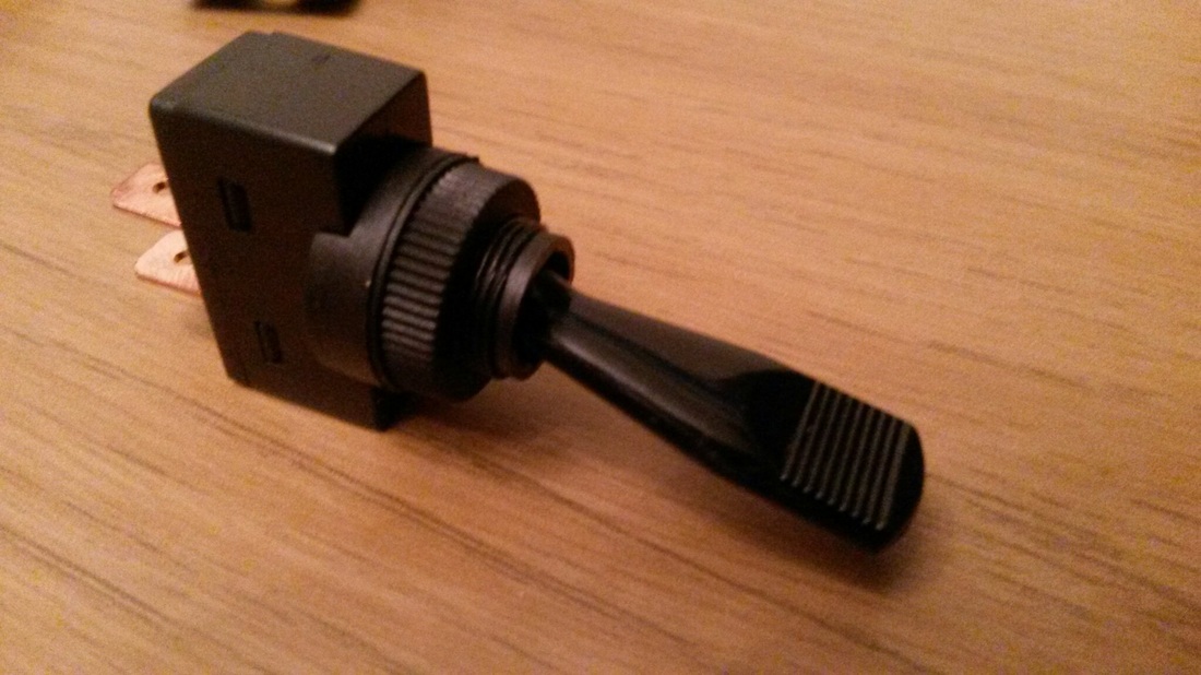
Off:On toggle switch
I have spent a lot of time redesigning all of the circuits in Microsoft Visio to encompass the new toggle switches. I will post the schematics separately.
I have spent a lot of time recently studying the Rover wiring diagrams so that I can understand how each system works within the car and ultimately so that I can reuse as much of the existing wiring where possible. This wiring schematic has been designed to power the electric reverse motor that I will be fitting, a modified starter motor. I wanted to include a few safety features to prevent the motor being operated whilst the car is in gear and/or whilst the handbrake is applied. This circuit is based on an additional Auxiliary battery being installed and I will be running a split charge system. A small motorbike battery will be connected to the Yamaha R1 engine loom to power the ECU, clocks and starter logic and a larger auxiliary battery will power all the car functions.
The New Auxiliary Relay in the schematic will be energised by the bike loom once the ignition is in Position 1 but the power will come via the Auxiliary battery. In order to reverse the car, the following conditions must be met; 1. Must be in neutral to energise the Reverse Relay 2. Handbrake must be off 3. Dash mounted toggle switch must be on - This will illuminate a warning LED and turn the reverse lights on 4. A floor mounted push switch is pressed sending power to the Reverse motor The freezing tempatures have limited the amount of time I have been spending in the garage but I have managed to make a good start on sorting the wiring loom out. 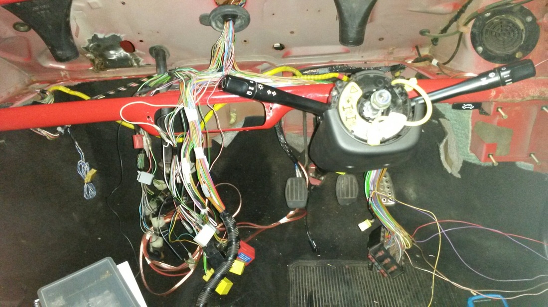 It might look like a big mess but its actually fairly easy to work with the loom once all the wrap is removed.
Working with the official Rover wiring circuit diagrams I was able to identify all of the injection specific wires and strip them out. I have updated copies of the diagrams to show what I have removed in case I need to add back in at a later date. A set of used Group 2 arches arrived yesterday that I picked up The Mini Forum for a decent price. They need a repaint but overall the condition is good and I can't wait to see what they look like fitted. 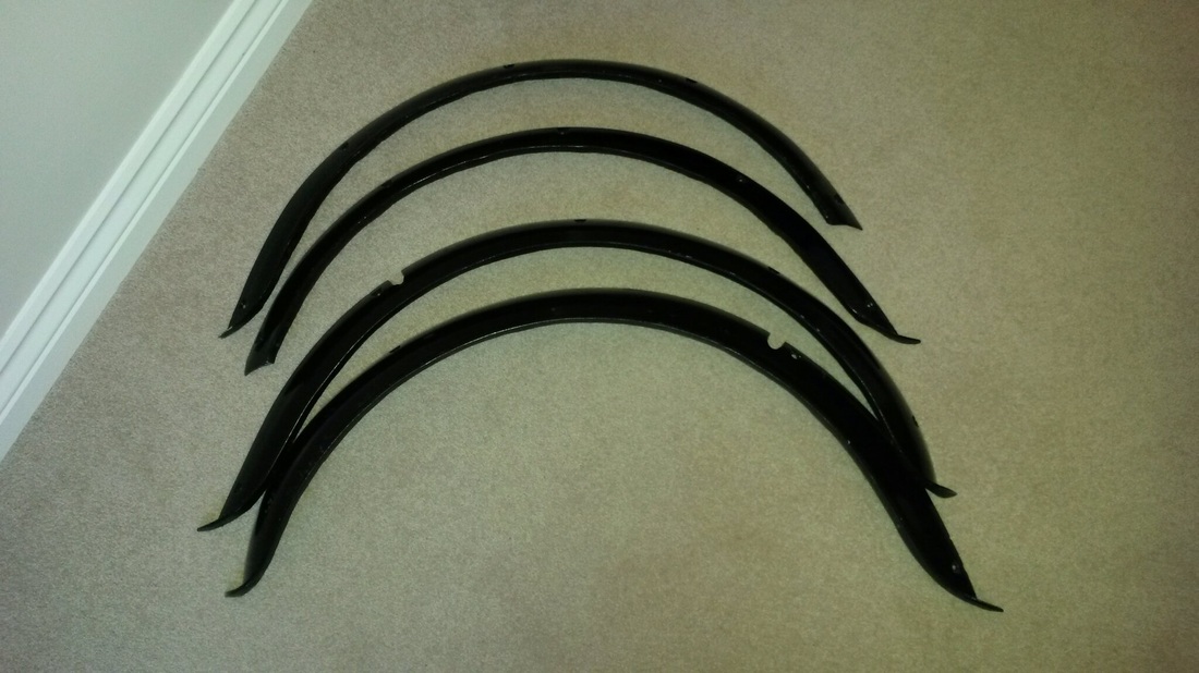 Whilst I am going to the hassle of transplanting a Yamaha R1 engine into the Cooper I thought I would take the opportunity to carry out a few exterior mods. I have always liked the look of MK1's so I thought why not add a few MK1 touches to this mini. I quick google for inspiration found this picture.  My Mini won't look exactly like this but this is the overall look I am going for.
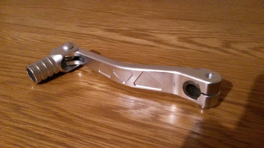 My new shifter arrived for the Yamaha R1 engine I'll soon be installing in the Cooper :-)
I haven't gone into much detail yet about my plans to install a Yamaha R1 engine in the front of the Cooper. I decided to go down this route over Christmas 2014 and a week later I had a 2003 R1 injection engine sitting in my garage. More to follow.... |
