|
Well it's been quite a while since I updated this blog so I thought I'd share what I've been up to. I've made quite a lot of progress with the build which includes starting lots of little sub-projects.
I have recently turned my hand to Arduino which is proving to be both fun to develop and it's opened a whole new world of possibilities. I started thinking about how I am going to drive the mechanical Smiths speedometer once I have the bike engine installed. The R1 motor uses a digital pulse to drive the standard clocks (which I will be running in the car) but that's no good for the mechanically driven Smiths gauge. An simple post on the Mini Forum resulted in someone suggesting I look at Arduino. Well fast forward a couple of weeks I have got a prototype code that will take the digital pulse from the R1, count it over a 1 second interval, convert to MPH, convert that to RPM to drive a DC motor connected to Smiths speedo cable to drive the gauge. It's essentially a digital-to-analog converter. I haven't been able to test it properly as I am still waiting for a DC motor to arrive but I will write up in more detail including my calculations and code when it's working.
0 Comments
I have spent a lot of time recently studying the Rover wiring diagrams so that I can understand how each system works within the car and ultimately so that I can reuse as much of the existing wiring where possible. This wiring schematic has been designed to power the electric reverse motor that I will be fitting, a modified starter motor. I wanted to include a few safety features to prevent the motor being operated whilst the car is in gear and/or whilst the handbrake is applied. This circuit is based on an additional Auxiliary battery being installed and I will be running a split charge system. A small motorbike battery will be connected to the Yamaha R1 engine loom to power the ECU, clocks and starter logic and a larger auxiliary battery will power all the car functions.
The New Auxiliary Relay in the schematic will be energised by the bike loom once the ignition is in Position 1 but the power will come via the Auxiliary battery. In order to reverse the car, the following conditions must be met; 1. Must be in neutral to energise the Reverse Relay 2. Handbrake must be off 3. Dash mounted toggle switch must be on - This will illuminate a warning LED and turn the reverse lights on 4. A floor mounted push switch is pressed sending power to the Reverse motor The freezing tempatures have limited the amount of time I have been spending in the garage but I have managed to make a good start on sorting the wiring loom out. 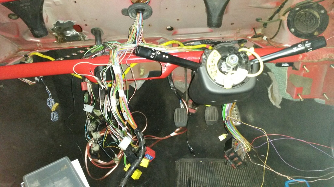 It might look like a big mess but its actually fairly easy to work with the loom once all the wrap is removed.
Working with the official Rover wiring circuit diagrams I was able to identify all of the injection specific wires and strip them out. I have updated copies of the diagrams to show what I have removed in case I need to add back in at a later date. |
