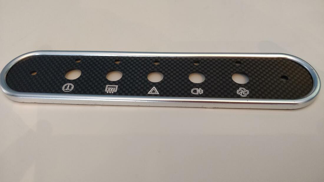
 In an effort to tie the interior together I have made this carbon fibre switch panel to match the carbon centre speedometer. I used my new CNC machine to engrave the logos and mill the holes accurately. The logos were created by downloading suitable png icons and converting them to svg's using Inkscape so they could be imported into Fusion360 and used to create tool paths. Once everything was machined I highlighted the logos by applying white enamel and then carefully wiping the excess away. Switch FunctionsFrom left to right, the switches functions are;
- Multi gauge - Used to toggle between different gauge screens and acknowledge/dismiss warnings. - Heated rear screen - Hazards - Rear fog light - Fan - Manual override to turn the radiator fan on.
0 Comments
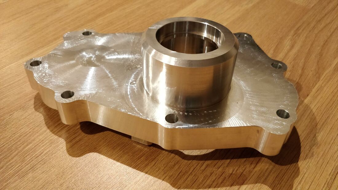 Having made good progress prototyping a supercharger conversion for the R1 motor, link to last post here I decided I would take the plunge and have the main casing part CNC machined. That proved to be a lot harder than expected. Finding a company willing to quote for the part was difficult. Most just didn't seem interested failing to return emails and calls before I had even disused a price with them.
Fortunately I discovered a guy in Greece who was able to make the part for a reasonable price in a short time frame. 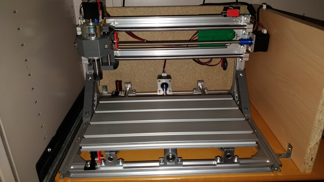 After the success of milking my own PCB for the DIY exup eliminator I decided I needed a new CNC machine with a larger work area and more precision.
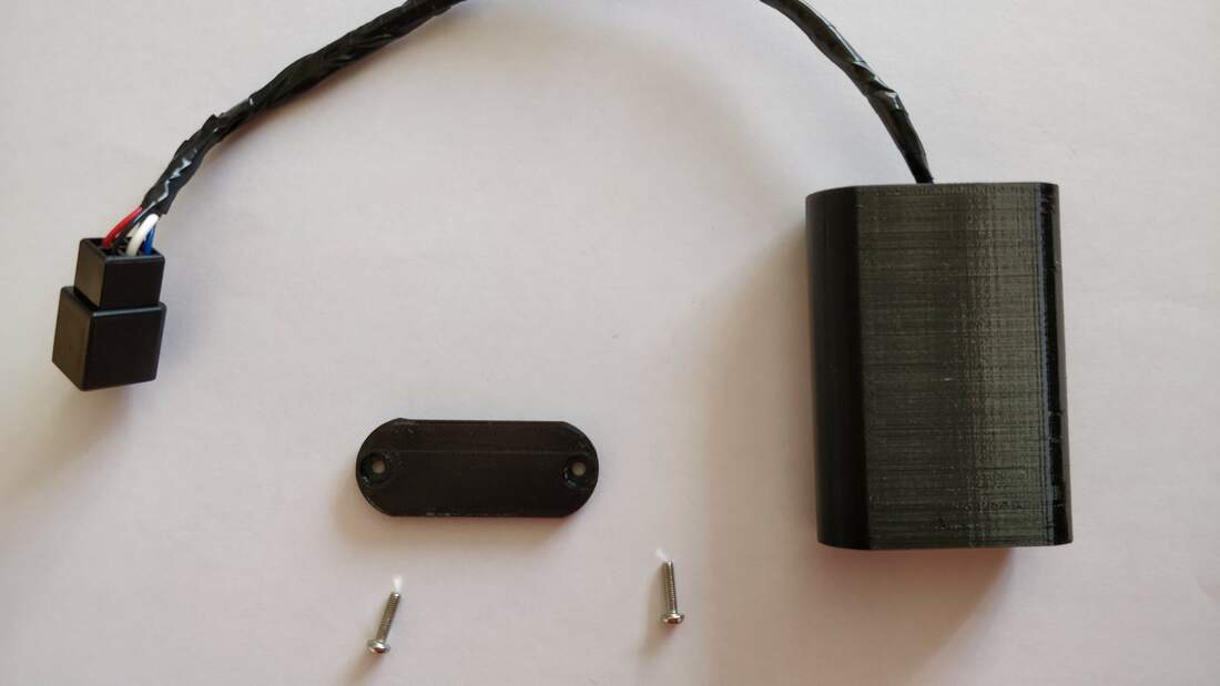 This is my Arduino controlled exup eliminator that will fool the Yamaha R1 ECU into thinking the exup valve is still connected thus preventing error code 17 on appearing on the gauge. How it worksIt has been a lot of work getting to this point. Lots of wires have been stripped out of the loom and modifications made so it can be run in the mini.
The video says it all. It lives!!!! The fault codes are expected. I don't have an exup, air or water temp sensor connected to the loom. 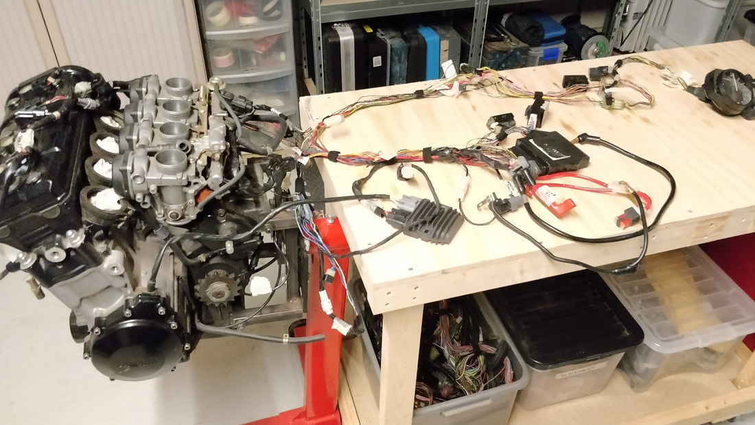 With the wiring loom modifications mostly complete it was time to offer it up to the engine and get it all the major components hooked up. The plan is to connect it to a battery so I can power up and check everything out and keep an eye on the fault codes if any appear.
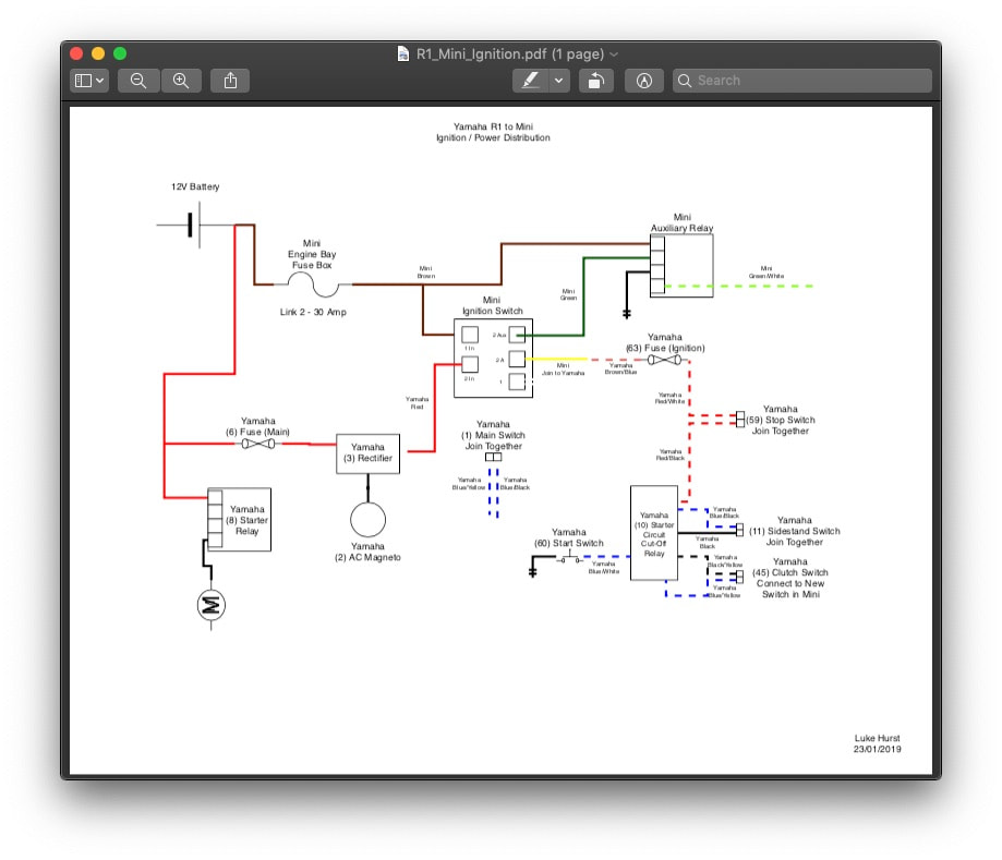 I have lost count of how many hours I have spent studying the Yamaha wiring loom. Hopefully it will pay off and I've come up with what should be a viable method of connecting the R1 loom to the Mini ignition/power distribution.
After a few very cold evenings spent in my garage I have just about stripped everything I can from the loom and I have identified all the main components. Before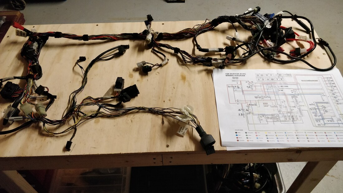 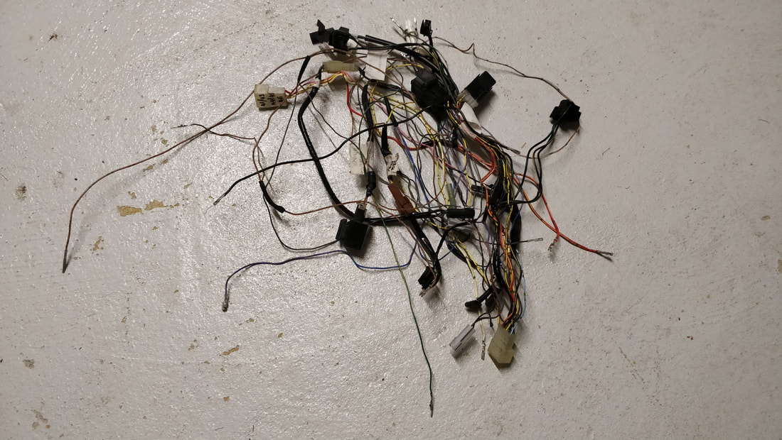 Progress with the R1 loom is being made. The picture shows all the wiring I have removed from the loom so far. Items removed from loom The huge task of sorting out the Yamaha R1 wiring loom has begun. I've started by removing almost all of the wrap covering the individual wires to make tracing and indentification easier.
The general idea is to identify all of the wires and then start stripping out the circuits that aren't required such as the lighting and horn. To identify the wires I am using a combination of the official Yamaha wiring diagram along with the Haynes manual version for my 2003 5PW engine. Once the loom is stripped back to essential circuits I will begin the task of converting it to car use such as disabling the lean sensor. |
