|
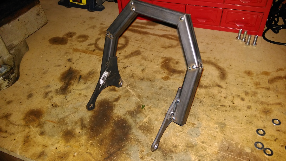
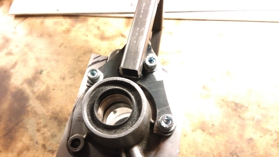
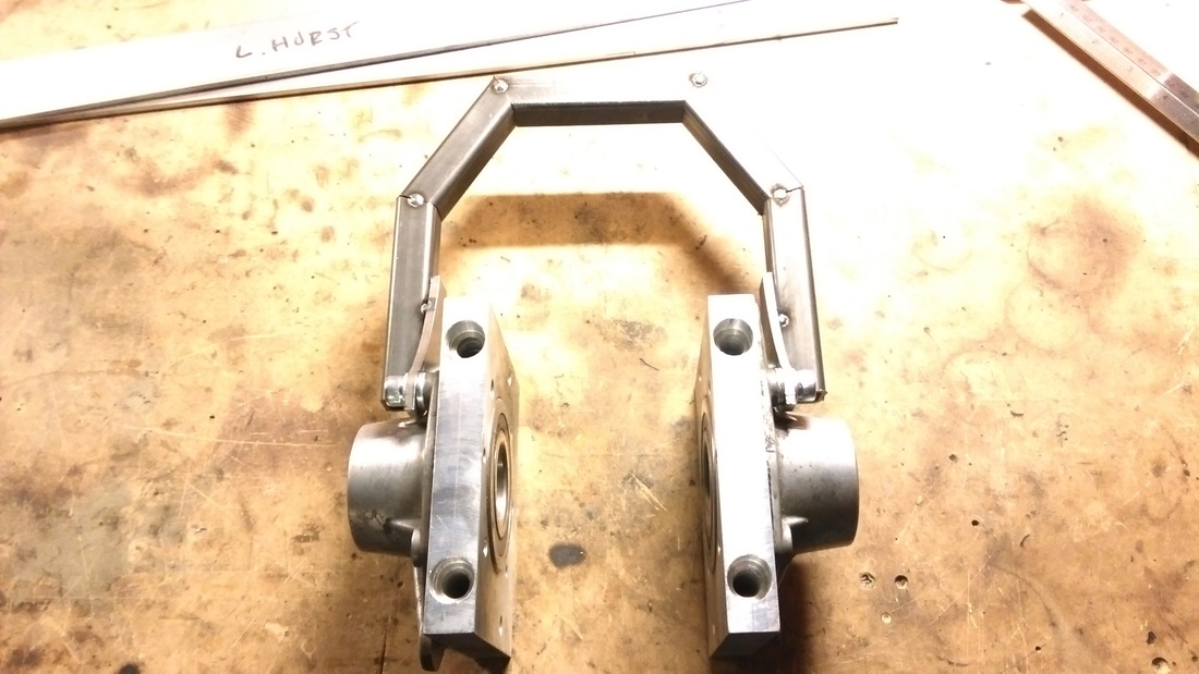
The most important bit of the build so far and perhaps the most critical to success is the differential hanger. It will ensure the correct chain-line and tension whilst the power of the engine is transferred through the chain into the drive shafts. My design attempts to overcome the challenges of having a solid mounting point whilst remaining compact enough to fit between the engine and subframe. FabricationI created a cardboard template of the chain-line between the engine sprocket and the rear differential sprocket. This allowed me to determine the amount of space I would need between the hanger and the differential. I also needed to ensure the hanger was the correct width once the differential is fitted so I measured and cut a block of wood to the same size as the diff to act as a spacer. 88mm to be exact. Once I had determined all the spacing, I marked out the critical dimensions on a piece of cardboard to help with the metal box section cuts. 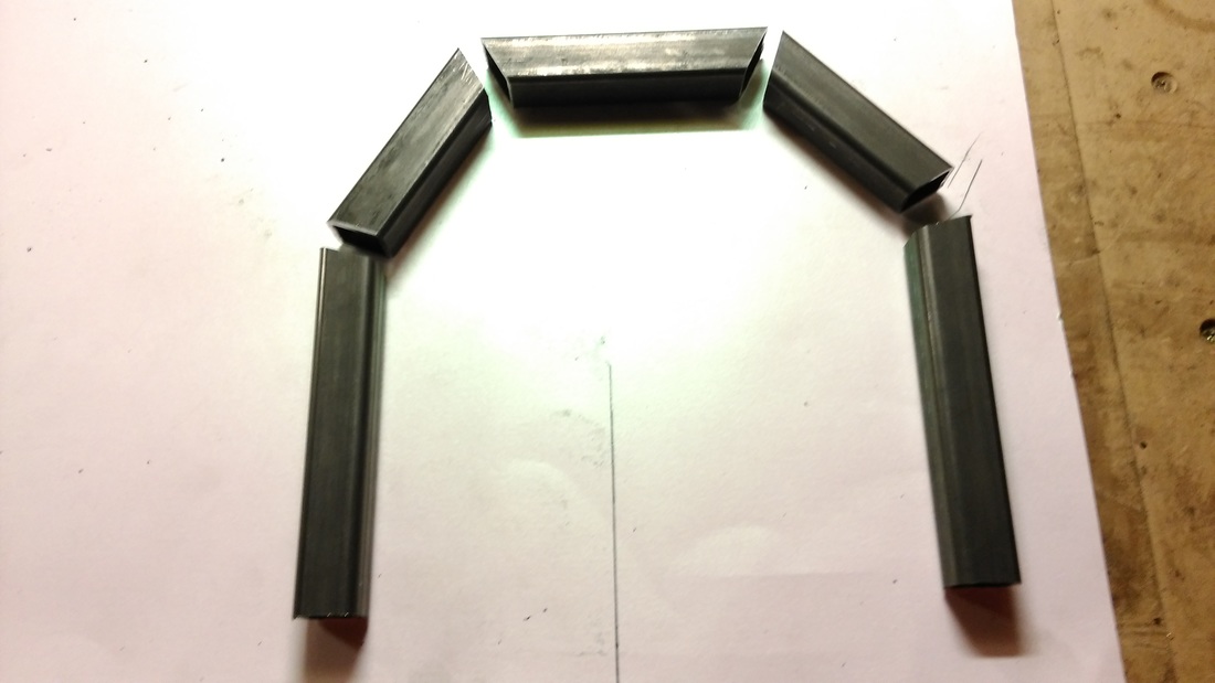 The pencil line was used to mark the hanger width from the right-hand cardboard edge. 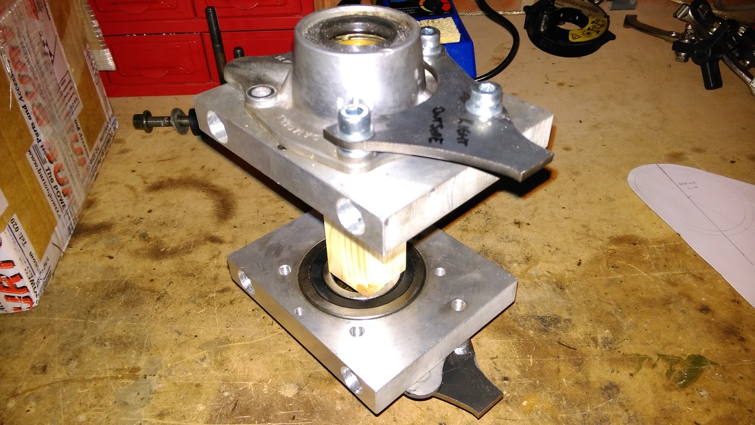 The wooden spacer used during fabrication to represent the differential CAD Brackets The differential kit I purchased from Westgarage was designed to have four large bolts pass through the bearing blocks in order to secure it to the engine frame. My installation does not allow enough space between the engine and subframe for this approach so I had to come up with another method. The obvious approach was having the mounts attach to the side of the bearing blocks however, the output covers are an odd shape I wanted to ensure a solid mounting. I decided to make a cardboard template of a bracket that seemed like it work. I then started contacting a few machine shops to have the brackets made but they were quoting silly prices to work form my cardboard template, so it was time to learn how to draw in CAD. I've dabbled with Photo editing in the past and I've tried Google Sketchup so I figured I would have a go at designing my own parts. My home pc is running Fedora (Linux) so I looked around for Open Source software and settled on LibreCAD It only produces 2D drawings but fine for what I require. 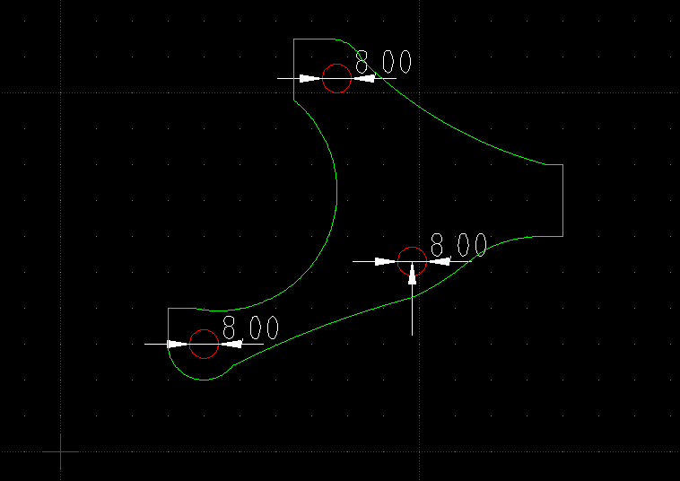 Here is the finished drawing I sent off to a laser cutter. They charged me £20 including materials and shipping to produce these for me and I received them within a week. I had to do a bit of dremel work on the output covers to get them to fit properly. The "ribs" on the covers needed to be re-shaped to allow the brackets to sit flat and I spaced them with washer to allow fine tuning of the position later. Here they are test fitted to the output covers 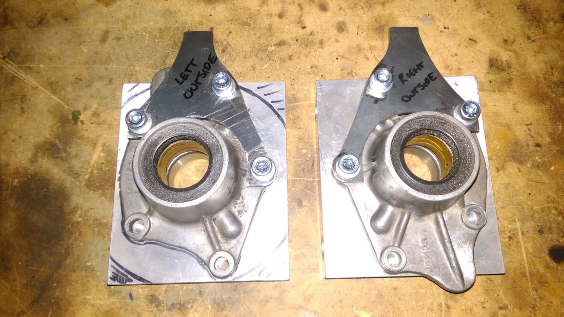 Once I had all the parts cut I started building the hanger. The welds are temporary tacks just in case I need to alter anything later. Part 2 will consist of fabricating the mounts that will attach the hanger to the engine frame. I will be using rod ends aka Rose Joints with a turnbuckle linkage so I can fine tune the length of the link thus applying/removing tension on the chain.
0 Comments
Your comment will be posted after it is approved.
Leave a Reply. |